
30% Glass Fiber Reinforced Nylon for General Engineering Parts
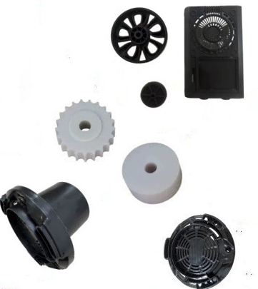
If you open an industrial gearbox, a dishwasher, or the engine bay of almost any modern car, you will find the same material doing structural work: 30% glass fiber reinforced nylon. It is the most widely used reinforced polyamide in general engineering, and the reason is practical — at 30% loading, PA6 and PA66 gain enough stiffness and heat resistance to replace die-cast metal in brackets, housings, gears and clips, while still filling complex geometry in a single shot.
This guide covers where GF30 is actually used in general engineering, which part families it suits best, and the design and molding details that decide whether a conversion succeeds.
Why General Engineering Settled on 30% Glass
Glass loading is a dial, and 30% is where the dial stops for most parts:
- GF15 — better surface, higher elongation, but often too compliant for load-bearing parts.
- GF30 — roughly triple the stiffness of unfilled nylon, HDT around 250 °C (PA66, dry), still moldable at 2 mm walls. The general-purpose structural choice.
- GF50 — maximum stiffness and creep resistance, but a cosmetic surface is hard to achieve and impact drops again.
For most general engineering parts, 30% delivers the stiffness the geometry needs while keeping a process window a production shop can hold shift after shift.
Typical Property Window
| Property (dry as molded, unless stated) | PA6-GF30 | PA66-GF30 |
|---|---|---|
| Tensile strength | 170–190 MPa | 180–200 MPa |
| Tensile modulus | 9,000–10,500 MPa | 10,000–11,500 MPa |
| Notched Charpy impact | 12–16 kJ/m² | 12–16 kJ/m² |
| HDT/A @ 1.8 MPa | 200–215 °C | 245–255 °C |
| Density | ~1.36 g/cm³ | ~1.37 g/cm³ |
| Mold shrinkage (flow / transverse) | 0.3% / 1.0% | 0.3% / 0.9% |
Typical dry-as-molded values for general-purpose grades. Confirm against your supplier's datasheet — and note that a part conditioned to 23 °C / 50% RH gives up roughly 35–45% of its dry stiffness and about 30% of its tensile strength, while notched impact improves.
Where GF30 Is Used in General Engineering
Structural Brackets, Mounts and Frames
The classic metal-replacement job. Console brackets, motor mounts, pump supports, sensor brackets, and conveyor side frames all use GF30 where the load is steady rather than shock. Typical wins: 40–60% weight reduction versus die-cast aluminium, no corrosion, and several machined parts consolidated into one molding. Design rule: load along the flow direction where possible, because transverse strength can be 30–40% lower.
Gears, Bearings and Wear Parts
GF30 runs dry against steel in lightly loaded gears, cams, rollers, and bearing cages. It is quieter than metal and needs no lubrication, which matters in food, textile and office equipment. For higher PV (pressure × velocity) conditions, specify a wear-modified grade with PTFE, silicone or MoS₂ — and keep in mind that absorbed moisture actually helps: dry-running GF30 can be abrasive to its steel counterface, conditioned parts are kinder.
Housings, Covers and Enclosures
Pump housings, valve bodies, fan shrouds, power-tool gearbox cases, and appliance structural frames. Here the driver is often dimensional stability plus heat resistance rather than pure strength — the 0.3/0.9% anisotropic shrinkage must be designed in, not discovered at first article.
Clips, Fasteners and Cable Management
Spring clips, cable ties, conduit clamps, snap-fit retainers. GF30 holds a clamp load better than unfilled nylon at elevated temperature, but elongation only runs 3–5%, so snap-fit beams must be short and thick with generous root radii. For aggressive snap geometries, either drop to GF15 or specify an impact-modified GF30.
Automotive and E-Mobility
Under-hood brackets, radiator end tanks, fan blades, pedal carriers, mirror brackets, and — with a halogen-free FR package — battery module spacers, busbar insulators and cell holders. Continuous service around 120–150 °C is realistic for heat-stabilised PA66-GF30.
Fluid Handling and Pumps
Cold-water pump bodies, valve bodies, filter bowls, impellers. Use a hydrolysis-resistant grade for hot water, coolants or steam-adjacent service, and remember that nylon's properties shift as it takes up water — design clearances and press fits at the conditioned dimension.
Design Notes That Decide Whether It Works
- Walls and ribs. Nominal wall 2.0–3.5 mm; ribs at 40–60% of the wall, with radii ≥ 0.5 × wall. GF30 stretches only 3–5% before breaking, so sharp corners are crack starters.
- Weld lines. Assume 40–70% of base strength, lower where fibers line up with the weld. Keep welds off the load path, or vent them well.
- Shrinkage and warpage. The 3:1 flow-to-transverse difference drives most warpage complaints. Use balanced or fan gating and run mold-flow with fiber orientation before cutting steel.
- Inserts and fasteners. Metal inserts create hoop stress in a stiff, low-elongation material. Use knurled or hex inserts with generous boss wall, and press them in warm, not cold.
- Wear on tooling. 30% glass abrades screws and gates. Bimetallic barrels and hardened gate inserts are standard practice, not upgrades.
Processing Snapshot
Dry to below 0.15% moisture (80 °C, 4–6 h, desiccant dryer). Melt 285–305 °C and mold 80–120 °C for PA66-GF30; PA6-GF30 runs about 30 °C cooler on the melt. Keep back pressure low (0.3–0.7 MPa) and gates generous (≥ 60% of wall) to preserve fiber length; screw speed moderate at 50–100 rpm.
When to Move Away from GF30
Step down to GF15 for cosmetic covers and aggressive snap fits. Step up to GF40/GF50 where deflection, not impact, governs and the surface can be hidden. Choose a wear-modified, hydrolysis-resistant, or flame-retardant variant whenever environment — not strength — is the binding constraint.
Key Takeaways
- GF30 is the default reinforced polyamide for general engineering because it balances stiffness, heat resistance and moldability.
- Best fits: structural brackets, gears and wear parts, housings, clips, automotive and pump components.
- Design for anisotropy and low elongation: generous radii, weld lines off load paths, and short thick snap beams.
Request a Free Design Review
Looking to reduce the cost of your next plastic injection molding project? Contact our engineering team today for a free consultation.
