
30% Glass Fiber Reinforced Nylon: Properties & Processing
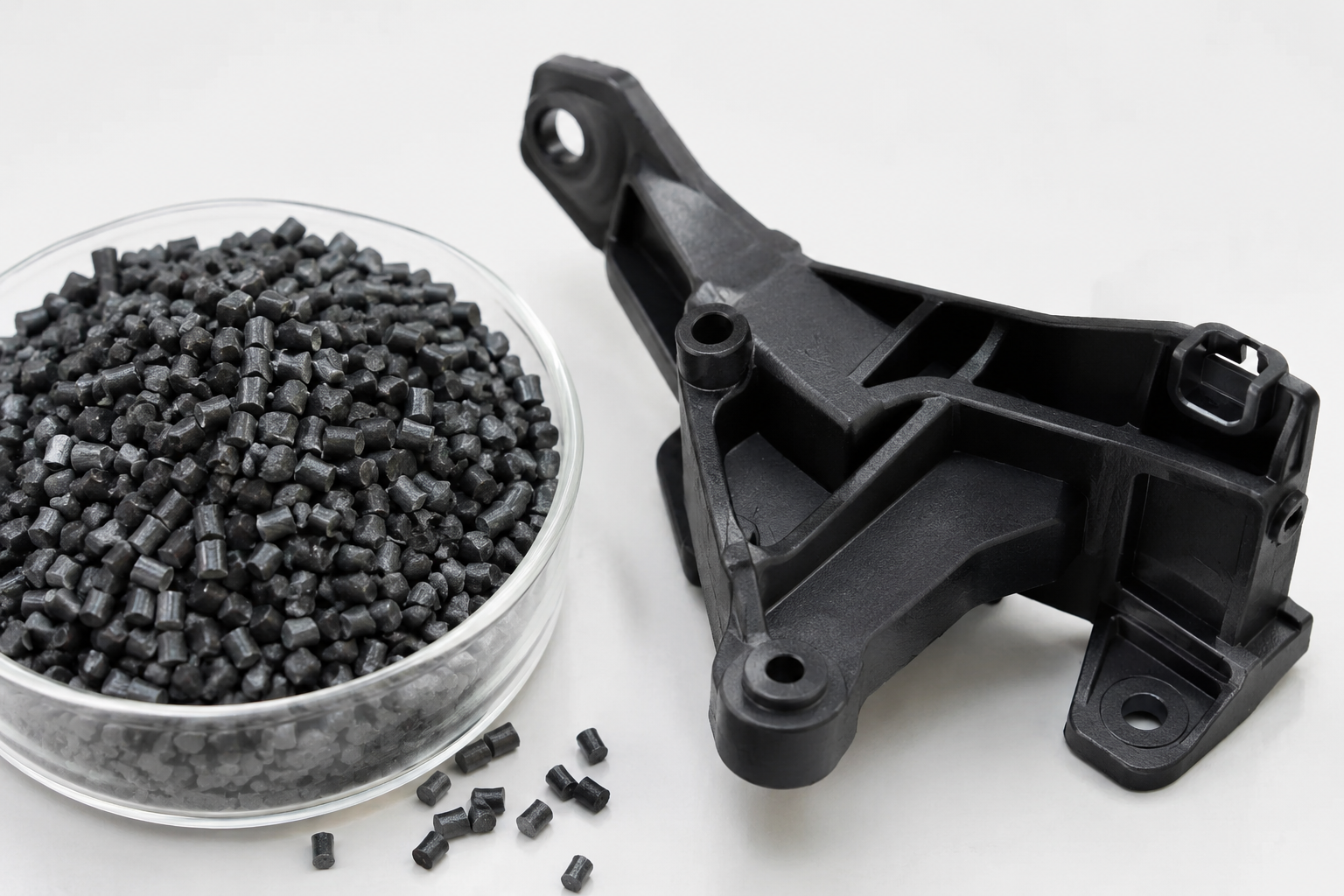
Glass fiber reinforcement is the fastest way to turn nylon from a tough general-purpose plastic into a structural one. At 30% loading, the compound hits a genuine sweet spot: roughly 2.3× the tensile strength and about 3× the stiffness of unfilled nylon, while still filling 1.5–2.0 mm walls on conventional equipment. This guide covers what 30% actually buys you in numbers, and how to process it without destroying the fibers that produce those numbers.
What "30% Glass Fiber Reinforced Nylon" Actually Means
Most commercial grades are built on PA66 (nylon 6/6) or PA6 (nylon 6), compounded with 30% by weight of short E-glass fiber — typically 10–13 µm in diameter, supplied as 3–4 mm pellets with fibers pre-dispersed and sized for adhesion to the polyamide matrix.
Two variables matter more than the headline percentage:
- Base resin. PA66-GF30 melts near 260 °C and delivers higher stiffness, better creep resistance, and higher HDT. PA6-GF30 melts near 220 °C, processes cooler, gives a better surface finish and slightly better impact, but absorbs noticeably more moisture.
- Retained fiber length. Pellets start with ~3 mm fibers. After plastication and filling, the average length in the molded part is usually 0.2–0.4 mm. Processing decides where you land inside that range, and retained length drives impact strength more than almost any other single variable.
Property Profile at a Glance
| Property | PA66-GF30 (DAM) | PA66-GF30 (50% RH) | PA6-GF30 (DAM) |
|---|---|---|---|
| Density (g/cm³) | 1.36–1.38 | 1.36–1.38 | 1.35–1.37 |
| Tensile strength (MPa) | 180–200 | 120–135 | 170–190 |
| Tensile modulus (MPa) | 10,000–11,500 | 6,500–7,500 | 9,000–10,500 |
| Flexural modulus (MPa) | 8,500–9,500 | 5,500–6,500 | 8,000–9,500 |
| Elongation at break (%) | 3–4 | 5–7 | 3.5–5 |
| Charpy notched impact (kJ/m²) | 12–16 | 15–20 | 12–16 |
| HDT/A @ 1.8 MPa (°C) | 245–255 | — | 200–215 |
| Melting point (°C) | 260 | 260 | 220 |
| Mold shrinkage, flow / transverse (%) | 0.3 / 0.9 | — | 0.3 / 1.0 |
| Water absorption, saturation (%) | ~5.5 | — | ~6.5 |
Typical values for general-purpose injection molding grades. Always validate against the datasheet for the exact grade you are buying.
Dry-as-Molded vs. Conditioned: Always Read Both Columns
Nylon is hygroscopic. A fresh GF30 part leaves the tool at maximum stiffness and minimum toughness. Over a few weeks at 23 °C / 50% RH it absorbs roughly 1.8–2.4% water by weight, which plasticizes the amorphous phase: modulus falls 35–45%, tensile strength drops about 30%, and notched impact improves by 40–60%.
Designing to DAM numbers is the single most common cause of brittle field failures. Size any part that sees impact or sustained load against conditioned data, and validate with parts conditioned to equilibrium in a humidity chamber rather than straight off the press.
Processing Window
Drying and Moisture Control
Dry at 80 °C for 4–6 hours in a dehumidifying hopper dryer (dew point ≤ −20 °C) to bring moisture below 0.15% — 0.20% absolute maximum. Above its melt point, nylon hydrolyzes: wet material loses molecular weight, shows splay and silver streaking, and can lose 30% or more of its impact strength. Regrind is the highest-risk stream because of its surface area; keep it sealed, dried separately, and capped at 15–25% of the shot.
Melt and Mold Temperature
- Melt temperature: 285–305 °C for PA66-GF30; 250–275 °C for PA6-GF30. Stay below ~310 °C (PA66) to avoid thermal degradation and black specks.
- Mold temperature: 80–120 °C. Hotter molds keep fibers below the surface (better cosmetics), raise crystallinity, and improve weld-line strength. Below 60 °C you get a fiber-rich skin, poor appearance, and high molded-in stress.
- Residence time: under 5–8 minutes; purge before extended stops.
Shear, Back Pressure, and Fiber Length Retention
Glass fiber is brittle and breaks under shear. To keep it long:
- Low back pressure (0.3–0.7 MPa) and low screw RPM (50–100 rpm).
- Generous gates and runners — gate thickness ≥ 50–60% of wall, ideally 1.0–1.5 mm on small parts; avoid pinpoint gates on thick sections.
- Medium-to-fast injection speed with a profiled fill to prevent jetting and shear burn.
- Wear-resistant hardware. Glass fiber abrades standard nitrided steel quickly: specify a bimetallic barrel and screw, and hardened mold steel (≥ HRC 52) for high-volume tools.
Design Rules That Prevent Field Failures
Walls, Ribs, and Weld Lines
Hold nominal walls at 2.0–3.5 mm; GF30 fills thin sections well, but the fiber-rich skin makes sub-1.5 mm walls behave brittle. Ribs at 40–60% of the adjoining wall, 0.5° draft, and radii of at least 0.5 × wall — sharp corners concentrate stress in a material that only stretches 3–4% before breaking. Assume weld lines carry 40–70% of base strength, and less where fibers align parallel to the weld; move welds off load paths and vent them properly.
Shrinkage, Anisotropy, and Warpage
GF30 shrinks about 0.3% along flow and 0.9% across it — a 3:1 anisotropy driven by fiber orientation. That differential is the main source of warpage in flat, ribbed, or center-gated parts. Counter it with balanced or fan gating, uniform wall thickness, and mold-flow simulation that includes fiber orientation, not just fill time. Cutting steel without a fiber-orientation study is the usual route to a warped first article.
Choosing Between GF15, GF30, and GF50
- GF15 — best surface finish, highest elongation, lowest warpage; housings, clips, cosmetic covers.
- GF30 — the default structural grade: metal-replacement brackets, fan blades, power-tool bodies, under-hood components.
- GF50 — maximum stiffness and creep resistance, but poorer surface, higher warpage, and 20–30% less elongation than GF30.
Key Takeaways
- 30% glass fiber lifts tensile strength by roughly 130% and roughly triples modulus versus unfilled nylon, at ~4% elongation.
- Design against conditioned (50% RH) data, never dry-as-molded.
- Dry to <0.15% moisture; run 285–305 °C melt and 80–120 °C mold for PA66-GF30.
- Protect fiber length with low back pressure, generous gates, and bimetallic hardware.
- Budget for 0.3/0.9% anisotropic shrinkage during mold design, not after it.
Request a Free Design Review
Looking to reduce the cost of your next plastic injection molding project? Contact our engineering team today for a free consultation.
