
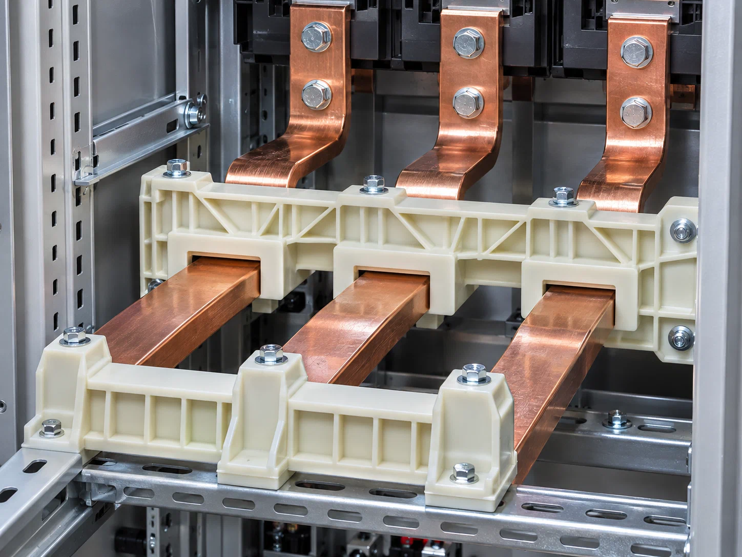
In industrial low-voltage distribution cabinets, switchgear assemblies, and electrical control systems, busbar insulation supports perform essential functions such as conductor positioning, phase separation, structural support, and mounting retention. Copper busbars must be installed in specific arrangements and at defined distances inside electrical enclosures. Supporting components must maintain accurate busbar positions while preserving reliable insulation distances and mechanical stability throughout operation. As switchgear designs become more compact and integrated, internal installation space becomes increasingly restricted, making busbar arrangements, connection points, and insulation structures more complex. Standard support components may not always accommodate special enclosure dimensions, busbar configurations, or mounting requirements, creating a need for customized plastic functional components.
A busbar support is more than a simple plastic mounting block. It is a functional component directly involved in the safety and structural design of electrical equipment. Through mounting holes, positioning slots, support surfaces, and fastening structures, it keeps busbars in their intended positions while maintaining insulation distances between different phases and between conductors and grounded structures. During normal operation, the support must withstand the weight of the busbars, fastening forces, and continuous thermal loading. During a short-circuit event, electromagnetic forces between busbars can also generate significant temporary mechanical loads. The support must therefore maintain sufficient structural integrity under the specified operating and fault-verification conditions. Cracking, loosening, or permanent deformation must not compromise the required insulation distances.
One common development challenge is dimensional misalignment after busbar installation or localized damage during fastening and operation. Consider a typical low-voltage switchgear development scenario involving multiple rows of copper busbars. The original support design meets basic installation requirements, but assembly inspection reveals deviations at certain mounting positions, with some screw bosses developing cracks. Further investigation shows that the issue is not limited to material strength. Wall thickness around screw bosses, mounting-hole positions, busbar loading directions, and support-point distribution also contribute to the problem. Simply selecting a stronger material without modifying the mounting structure and load path may not resolve the issue. A more effective approach is to review support locations, screw-fastening structures, reinforcing ribs, and busbar contact areas to achieve more balanced mechanical load distribution.
Maintaining insulation distances is another critical aspect of support design. Required clearances and creepage distances between busbars, as well as between conductors and grounded structures, must comply with the electrical design requirements of the assembly. Positioning bosses, separating walls, grooves, and mounting features all influence the actual insulation paths. If the component geometry is too compact or dimensional variation occurs during molding, the original insulation distances may be affected. Design dimensions must therefore be established according to rated voltage, insulation requirements, pollution degree, and actual installation conditions rather than simply minimizing component size. Supports with multiple phase-separation sections also require consistent wall thickness, separation heights, and assembly positions.
In addition to mechanical strength and insulation geometry, flame retardancy is an important consideration. Electrical distribution equipment contains energized connections and components that generate heat during operation. Insulating supports must therefore be evaluated for flame-retardant behavior, heat resistance, and electrical properties according to the equipment's safety requirements. Some applications also require attention to resistance to electrical tracking, particularly where humidity, contamination, or prolonged electrical stress may affect surface insulation performance. PA66, PBT, and other suitable flame-retardant engineering plastics may be evaluated depending on the application. The final material selection must consider actual component thickness, operating temperature, and complete equipment verification requirements. A material's flame-retardant classification alone does not establish the safety compliance of the entire electrical assembly.
For customized busbar supports, product geometry and mold development must be considered together. Screw bosses, busbar positioning slots, separating walls, and reinforcing ribs are often concentrated within limited spaces. Excessive wall-thickness variation or unsuitable gate placement can lead to uneven filling, differential shrinkage, and deviations in critical dimensions. The relative positions of multiple busbar mounting points should be defined through clear dimensional datums during mold development. For supports requiring precise assembly, demolding deformation, hole dimensions, and dimensional consistency between production batches also need to be controlled. Appropriate reinforcement, wall-thickness transitions, and mold cooling design can reduce dimensional variation and improve compatibility between the support, copper busbars, and enclosure structure.
TechInherit specializes in customized specialty functional plastic components and can evaluate support structures and manufacturing solutions based on equipment drawings, installation space, busbar arrangements, and mechanical requirements provided by switchgear manufacturers. For components with special mounting dimensions, complex insulation barriers, or non-standard fastening methods, material modification, structural optimization, mold development, and precision injection molding can be coordinated throughout the development process. For projects involving specific electrical safety requirements, material specifications, component validation conditions, and complete equipment testing must also be confirmed with the equipment manufacturer to ensure that customized components are suitable for the final assembly.
From initial sampling to volume production, busbar insulation supports require systematic dimensional, mechanical, and electrical validation. In addition to inspecting mounting holes, positioning slots, and critical insulation dimensions, testing may include mechanical loading, short-circuit withstand verification as applicable, heat resistance, flame retardancy, and insulation performance. For switchgear assemblies that have already undergone design verification, changes to support material, geometry, or mounting arrangements may also affect the original verification results. Any modification must therefore be incorporated into the equipment manufacturer's validation process. Combining component design, mold development, injection molding quality, and complete assembly testing is essential to ensuring reliable performance in actual operating environments.
For low-voltage switchgear manufacturers, the value of customized busbar insulation supports extends beyond simply securing copper conductors. It lies in resolving the complex interaction between special busbar layouts, limited installation space, insulation requirements, and mechanical loading. When standard supports cannot accommodate equipment geometry, or existing components develop mounting deviations, fastening cracks, or insufficient long-term stability, customized functional plastic components can provide a more targeted solution. Through structural optimization and precision manufacturing, manufacturers can improve busbar installation consistency, reduce assembly adjustments and maintenance costs, and enhance the structural reliability of electrical equipment.
Request a Free Design Review
Looking to reduce the cost of your next plastic injection molding project? Contact our engineering team today for a free consultation.
